.
 I went back to the salvage yard where I
bought the patch panel and liberated this frame from the same 1933 Plymouth.
The body was very rotten, and had about 12" of river bottom mud laying on the
floorboards.
It took the wife and I about 4 hours to get it and a Mustang II front
suspension. Not to bad for a Saturday morning.
I went back to the salvage yard where I
bought the patch panel and liberated this frame from the same 1933 Plymouth.
The body was very rotten, and had about 12" of river bottom mud laying on the
floorboards.
It took the wife and I about 4 hours to get it and a Mustang II front
suspension. Not to bad for a Saturday morning.
Click on this link to view the Frame.pdf. It isn't completely accurate yet, but for the most part it is.
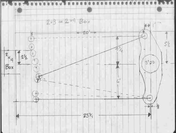 A person would think after spending nearly $1000.00 for a rear suspension they would include a diagram that looked sort of like this. I guess not though. At any rate the lower bar should have a 5° slope for the initial setup.
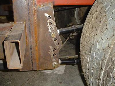 I used the Art Morrison parts for a pattern that was flat at the top. If I was to do this again I would not use 2"X4" for these uprights. I would use 2"X2" and I would trim some from the 4 link brackets. That would move the front part of the upright back 2"-3", which would leave more room for my butt.
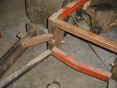 You can see my version of triangulating this frame. Notice the lower diagonal brace running from the bottom of the 4 link bracketsto the transmission cross member attaching welds.
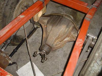 The Dana 60 takes up a lot of space under the frame rails. The pinion angle is 0°, since the 4 link should control pinion wrap up better than leaf springs. Leaf springs usually have 3° of downward angle. Than as power is appied the pinion starts climbing, so at road speed it matches the angle of the engine.